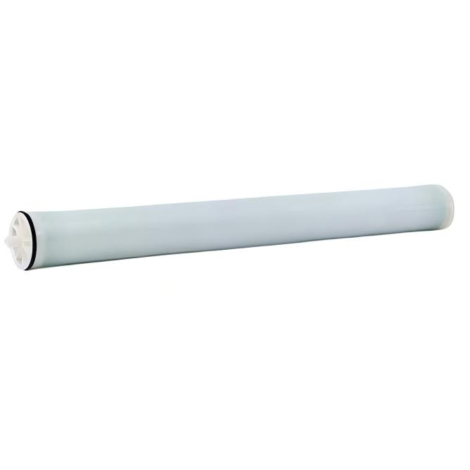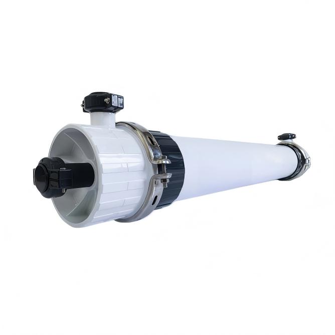
Scraped Surface Crystallizer is designed for high-load, high-salinity, and high-viscosity wastewater crystallization and drying applications.
By combining forced circulation, scraped surface heat transfer, and controlled crystallization, it enables stable solid–liquid separation and efficient moisture removal.
Scraped Surface Crystallizer - High-Load Solid/Liquid Crystallization & Drying System
The Scraped Surface Crystallizer is engineered for wastewater streams where conventional evaporation or crystallization systems struggle due to scaling, fouling, or high solids content.
The rotating scraper continuously removes deposits from the heat transfer surface, ensuring stable heat exchange and controlled crystal growth during long-term operation.
Key Features

System Placement
• Installed downstream of MVR or other evaporative concentration units for final drying
• Used as a finishing stage in zero liquid discharge (ZLD) systems to produce handleable solid waste
• Positioned after primary waste concentration or membrane units to reduce volume
Typical Applications
• Concentrated brine and mother liquor from evaporators
• High-hardness wastewater from chemical and industrial processes
• High-viscosity waste streams such as pesticide, lithium battery wastewater
• Landfill leachate and complex mixed waste requiring solidification
Scraped Surface Crystallization & Drying Process Overview

Step 1 – Concentrated Feed Introduction
High-salinity or high-solid wastewater is fed into the crystallizer under controlled flow.
Step 2 – Heat Transfer & Crystallization
Heat is transferred through scraped surfaces while crystals form in the circulating slurry.
Step 3 – Continuous Scraping
Rotating scrapers remove deposits from heat exchange surfaces to prevent fouling.
Step 4 – Solid–Liquid Separation
Crystallized solids are concentrated and separated from the liquid phase.
Step 5 – Drying & Discharge
Solids are further dried to reduce moisture content before discharge or disposal.
Technical Specifications
The following performance data is based on standard testing conditions. Actual performance may vary depending on feed water quality and operating parameters.
| Model |
Treatment Capacity |
Annual Capacity |
Specific Steam Consumption |
Steam Consumption |
Installed Power |
Overall Dimensions |
Weight |
Operating Weight |
| t/h | t/year |
(t steam / t feed) |
kg/h | kW | (L×W×H, mm) | kg | kg | |
| EET50 | 0.05 | 300 | 1.2 | 60 | 2 | 2641x1098x2161 | 1420 | 1620 |
| EET150 | 0.15 | 900 | 1.2 | 180 | 3 | 3700x1088x2159 | 1852 | 2252 |
| EET250 | 0.25 | 1500 | 1.2 | 300 | 8 | 4992x1445x2739 | 3800 | 4800 |
| EET375 | 0.375 | 2250 | 1.2 | 450 | 11 | 5489x1541x2841 | 5360 | 6560 |
| EET500 | 0.5 | 3000 | 1.2 | 600 | 16 | 4208x2678x3808 | 7500 | 9500 |
| EET750 | 0.75 | 4500 | 1.2 | 900 | 23 | 5365x2958x3678 | 9260 | 11660 |
| EET1000 | 1.0 | 6000 | 1.2 | 1200 | 27 | 6514x3358x3790 | 11965 | 17045 |
Note: Performance data are based on standard operating conditions (20 h/day, 300 days/year). Actual results may vary depending on feed characteristics and site conditions.


Leave a Message
Scan to wechat :

Scan to Whatsapp :


 Product categories